ICU
The ICU is a hardware device connecting the logical part (the API) with the mechanical part (the hardware). The ICU communicates both on the CAN network directly to the nodes and motors, and also via ethernet to the API. There is at least one ICU in every Eton Ingenious installation, but may be more depending on the size of the system and the total number of stations.
There are currently two revisions of the ICU, with the first being gradually phased out
- ICUv1 - No screen
- ICUv2 - Touchscreen, built in battery, more robust CAN communication
The ICU should be positioned together with the hardware system due to cable length limitations.
Configuration
| # | Description |
|---|---|
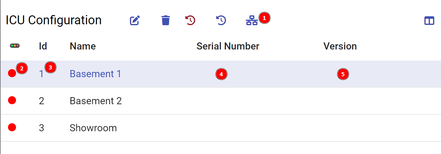
| 1 | Setup ICU - This button is used to configure an existing or new ICU. This brings up the dialog for ICU Setup. |
| 2 | Online status of ICU. 🟢 = Online, 🔴 = Offline , 🟡 = Online but not producing a heartbeat. |
| 3 | Id of ICU. ICUs are usually numbered starting with 1 and going up. |
| 4 | Serial number - This is the serial number of the ICU. |
| 5 | Version - The software version the ICU is running. Version 1.0.0 means it's running an ad-hoc build and not an official release. |
Context Menu
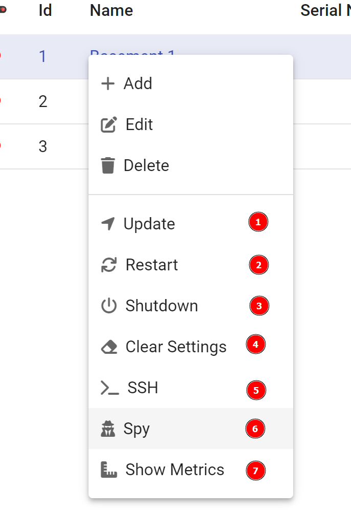
Right-clicking (or long press on Android) on a row will bring up the context menu.
| # | Description |
|---|---|
| 1 | Update the ICU software. Can be updated with local zip file or from online repository. |
| 2 | Restart the ICU. Restarting will first stop all lines and stations for about 10 seconds, then the actual restart is done. Normally ICU is operation again with 1 minute. |
| 3 | Shutdown the ICU. ⚠️ This should be used with care, as the ICU cannot be remotely powered back on. |
| 4 | Clear the settings. This will clear all settings on the ICU device and make it discoverable again. It is recommended to clear the settings of an ICU if you are going to replace the unit, as connecting an already configured ICU to the network can cause interference. |
| 5 | Connect a secure shell session to the ICU. This is only for experts. |
| 6 | Spy on CAN traffic going in and out from ICU. |
| 7 | Show metrics for this unit |
ICU Setup
| # | Description |
|---|---|
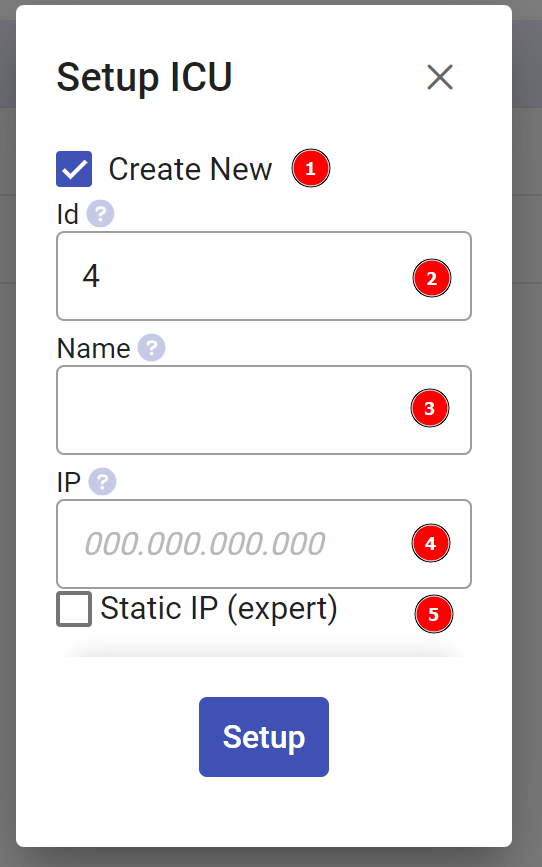
| 1 | Create New - Check this if you want to create a new ICU, uncheck to instead select an existing ICU from a dropdown that you want to configure. |
| 2 | Enter ICU id (Only shown when creating new ICU) |
| 3 | Enter ICU name (Only shown when creating new ICU) |
| 4 | Enter IP of ICU (Required) - The ICU should normally be configured with a static IP address, enter the IP here (only digits and dots) |
| 5 | Set a static address on ICU - This can be used to set a static IP for an ICU that has a DHCP assigned IP, or re-configure an ICU that already has a static IP. Checking this option will display further options where it is possible to set the IP, Gateway and DNS server for the ICU. |
Network Settings
The Network Settings dialog will allow you to configure the network options for the ICU. This is used mainly for when you already have a correctly set up ICU and you are updating network options, for instance switching between a DHCP assigned IP and a fixed IP.
These settings are only available when you are able to reach the ICU, so not when you have an incorrectly set up unit.
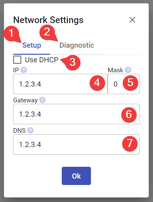
Setup (1)
Tab to view or change the current settings.
Diagnostics (2)
View diagnostic network information for the ICU
Use DHCP (3)
Using DHCP will disable the rest of the settings, as in this mode the configuration is managed by the router automatically.
It is very common that DHCP services have been disabled on production networks, meaning this option will not work.
It is always recommended that the ICU is assigned to a fixed IP, either on the router or manually with these settings.
IP (4)
This is the IP that should be assigned to the ICU. This value should be provided by the network administrator.
Mask (5)
This is the netmask that the ICU will use. This value should be provided by the network administrator.
An incorrectly configured netmask may cause communication issues with ICU.
Netmasks can use two different formats. It can either be presented as "192.168.1.3/26" where "26" would be the netmask, or sometimes the netmask value is provided in the alternative format which looks like an IP address for instance "255.255.255.192". In this case please use the chart below to convert it to a number.
| Number | Alt Format | Number | Alt Format | Number | Alt Format |
|---|---|---|---|---|---|
| 32 | 255.255.255.255 | 21 | 255.255.248.0 | 10 | 255.192.0.0 |
| 31 | 255.255.255.254 | 20 | 255.255.240.0 | 9 | 255.128.0.0 |
| 30 | 255.255.255.252 | 19 | 255.255.224.0 | 8 | 255.0.0.0 |
| 29 | 255.255.255.248 | 18 | 255.255.192.0 | 7 | 254.0.0.0 |
| 28 | 255.255.255.240 | 17 | 255.255.128.0 | 6 | 252.0.0.0 |
| 27 | 255.255.255.224 | 16 | 255.255.0.0 | 5 | 248.0.0.0 |
| 26 | 255.255.255.192 | 15 | 255.254.0.0 | 4 | 240.0.0.0 |
| 25 | 255.255.255.128 | 14 | 255.252.0.0 | 3 | 224.0.0.0 |
| 24 | 255.255.255.0 | 13 | 255.248.0.0 | 2 | 192.0.0.0 |
| 23 | 255.255.254.0 | 12 | 255.240.0.0 | 1 | 128.0.0.0 |
| 22 | 255.255.252.0 | 11 | 255.224.0.0 | 0 | 0.0.0.0 |
Gateway (6)
This is the IP for the gateway used by the ICU. This value should be provided by the network administrator.
An incorrectly configured value may lead to communication issues.
DNS (7)
This is the IP for the DNS server used by the ICU. This value should be provided by the network administrator.
This is not strictly required and may usually be set to the same value as the gateway.
Heartbeat
The ICU will continuously send out a heartbeat request to the API to verify that the API is processing messages correctly. If a heartbeat response is not detected then the ICU will stop the lines and stations, to not run in a state where the API possibly cannot process the updates it sends.
If the ICU is not sending heartbeats but indicates online, the status indicator will show yellow. This could be due to the ICU running an older software version and needing an update.